Lab 2: Digital I/O with Arduino
- Due Sep 13, 2017 by 10:30am
- Points 10
- Submitting a file upload
- File Types pdf
Readings in Physical Computing
- Ch 6. pgs 87-136 (this week and next week)
- Ch 7: Serial Communication [137-143; 149-150; 153-161]
Before the lab
You should have already successfully installed the Arduino environment on your laptop, built the LED circuit, and successfully load/run the “blink” program to make the LED blink. Congratulations!
In lab exercise
Objective
In this lab, we explore some of the digital features of the Arduino Board. Specifically, we’ll be looking at:
- Pulse Width Modulation (PWM) which “fakes” analog behavior using digital signals
- Serial communication with the laptop allowing for greater design flexibility
In exploring these features, we will use Arduino to not just blink a single LED, but to control and fade several LEDs at once.
Activity
PART 1: FROM BLINKING TO FADING
1. Start with the LED circuit you built for the “Blinking LED” Assignment. For that assignment, we used pin 13 to control the LED and make it blink. Ardiuno has several pins marked PWM which support Pulse Width Modulation. The example code uses Pin 9, so simply move the controlling wire from Pin 13 to Pin 9. 2. Load the example code from the Arduino Sketchbook (File‐>Examples‐>Analog‐>Fading). Load this onto the Arduino and watch the LED Fade.
PART 2: FADING 3 LEDS
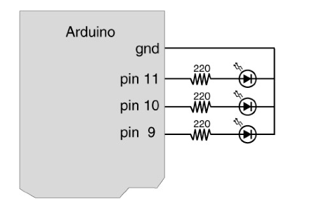
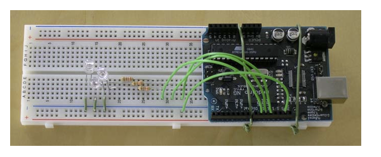
3. Extend your circuit so that it includes 3 LEDs according to the diagrams below. Notice Pins 9, 10, and 11 are all marked PWM.
4. The following code dims the 3 LEDs according to a pattern. Look at the code and make sure you know what each line does:
/*
* Code for cross-fading 3 LEDs, red, green and blue, or one tri-color LED, using PWM
* The program cross-fades slowly from red to green, green to blue, and blue to red
* The debugging code assumes Arduino 0004, as it uses the new Serial.begin()-style functions
* Clay Shirky <clay.shirky@nyu.edu>
*/

// Output
int redPin   = 9;   // Red LED,   connected to digital pin 9
int greenPin = 10;  // Green LED, connected to digital pin 10
int bluePin  = 11;  // Blue LED,  connected to digital pin 11

// Program variables
int redVal   = 255; // Variables to store the values to send to the pins
int greenVal = 1;   // Initial values are Red full, Green and Blue off
int blueVal  = 1;

int i = 0;     // Loop counter
int wait = 50; // 50ms (.05 second) delay; shorten for faster fades
int DEBUG = 0; // DEBUG counter; if set to 1, will write values back via serial

void setup()
{
  pinMode(redPin,   OUTPUT);   // sets the pins as output
  pinMode(greenPin, OUTPUT);
  pinMode(bluePin,  OUTPUT);
  if (DEBUG) {           // If we want to see the pin values for debugging...
    Serial.begin(9600);  // ...set up the serial ouput on 0004 style
  }
}

// Main program
void loop()
{
  i += 1;      // Increment counter
  if (i < 255) // First phase of fades
  {
    redVal   -= 1; // Red down
    greenVal += 1; // Green up
    blueVal   = 1; // Blue low
  }
  else if (i < 509) // Second phase of fades
  {
    redVal    = 1; // Red low
    greenVal -= 1; // Green down
    blueVal  += 1; // Blue up
  }
  else if (i < 763) // Third phase of fades
  {
    redVal  += 1; // Red up
    greenVal = 1; // Green low
    blueVal -= 1; // Blue down
  }
  else // Re-set the counter, and start the fades again
  {
    i = 1;
  }

  analogWrite(redPin,   redVal);   // Write current values to LED pins
  analogWrite(greenPin, greenVal);
  analogWrite(bluePin,  blueVal);

  if (DEBUG) { // If we want to read the output
    DEBUG += 1;     // Increment the DEBUG counter
    if (DEBUG > 10) // Print every 10 loops
    {
      DEBUG = 1;     // Reset the counter

      Serial.print(i);       // Serial commands in 0004 style
      Serial.print("\t");    // Print a tab
      Serial.print("R:");    // Indicate that output is red value
      Serial.print(redVal);  // Print red value
      Serial.print("\t");    // Print a tab
      Serial.print("G:");    // Repeat for green and blue...
      Serial.print(greenVal);
      Serial.print("\t");
      Serial.print("B:");
      Serial.println(blueVal); // println, to end with a carriage return
    }
  }
  delay(wait); // Pause for 'wait' milliseconds before resuming the loop
}
PART 3: SERIAL COMMUNICATIONS
5. Up until now, the Arduino board has been operating on autopilot once you’ve uploaded the program. In this step, you will be using Arduino’s Serial Communication feature. Here is the code. Look at the code and make sure you know what each line does.
/*
 * Serial RGB LED
 * ---------------
 * Serial commands control the brightness of R,G,B LEDs
 *
 * Command structure is "<colorCode><colorVal>", where "colorCode" is
 * one of "r","g",or "b" and "colorVal" is a number 0 to 255.
 * E.g. "r0"   turns the red LED off.
 *      "g127" turns the green LED to half brightness
 *      "b64"  turns the blue LED to 1/4 brightness
 *
 * Created 18 October 2006
 * copyleft 2006 Tod E. Kurt <tod@todbot.com
 * http://todbot.com/
 */

char serInString[100];  // array that will hold the different bytes of the string. 100=100characters;
                        // -> you must state how long the array will be else it won't work properly
char colorCode;
int colorVal;

int redPin   = 9;   // Red LED,   connected to digital pin 9
int greenPin = 10;  // Green LED, connected to digital pin 10
int bluePin  = 11;  // Blue LED,  connected to digital pin 11

void setup() {
  pinMode(redPin,   OUTPUT);   // sets the pins as output
  pinMode(greenPin, OUTPUT);
  pinMode(bluePin,  OUTPUT);
  Serial.begin(9600);
  analogWrite(redPin,   127);   // set them all to mid brightness
  analogWrite(greenPin, 127);   // set them all to mid brightness
  analogWrite(bluePin,  127);   // set them all to mid brightness
  Serial.println("enter color command (e.g. 'r43') :");
}

void loop () {
  // clear the string
  memset(serInString, 0, 100);
  //read the serial port and create a string out of what you read
  readSerialString(serInString);

  colorCode = serInString[0];
  if( colorCode == 'r' || colorCode == 'g' || colorCode == 'b' ) {
    colorVal = atoi(serInString+1);
    Serial.print("setting color ");
    Serial.print(colorCode);
    Serial.print(" to ");
    Serial.print(colorVal);
    Serial.println();
    serInString[0] = 0;                   // indicates we've used this string
    if(colorCode == 'r')
      analogWrite(redPin, colorVal);
    else if(colorCode == 'g')
      analogWrite(greenPin, colorVal);
    else if(colorCode == 'b')
      analogWrite(bluePin, colorVal);
  }

  delay(100);  // wait a bit, for serial data
}

//read a string from the serial and store it in an array
//you must supply the array variable
void readSerialString (char *strArray) {
  int i = 0;
  if(!Serial.available()) {
    return;
  }
  while (Serial.available()) {
    strArray[i] = Serial.read();
    i++;
  }
}
Homework
- Design a good diffuser for your RGB LEDs (e.g. ping pong ball, Styrofoam, etc)
- Change the code so that you can control the RGB values with multiple key presses. For example,pressing ‘r’ 5 times will set the brightness to 50% (or brightness = 127) and pressing ‘r’ 10 times will set it to 100% (or brightness = 255)
- (Optional) Come up with other ways of controlling the colors of the LEDs using the keyboardHere’s your chance to be creative. You can show off to your friends next week. Example: Read colors and set the appropriate RGB values like “orange” might set r=70%, g=50%, and b=0%.
 Find Rubric
