Lab 4: Sensing: FSR & Photocells and Serial Communication with Processing
- Due Sep 27, 2017 by 10:30am
- Points 10
- Submitting a file upload
- File Types pdf
Readings
- Physical Computing: Pg 284-289
- Read “Getting Started” at processing.org/tutorials/gettingstarted/ Links to an external site.
- Look at the video and/or text tutorials of Processing at processing.org/tutorials/ Links to an external site.. Programming Processing is a little different from programming Arduino so make sure you familiarize yourself with some of the basics.
Before the Lab
You should have already completed your color mixer and come up with some way to control the LEDs with 2 or 3 pots.
In Lab Exercise
Objective
In the past lab, we explored potentiometers (or “pot” for short) which are analog sensors that measure rotation. In this week’s lab, we’ll be exploring two other analog sensors. The first sensor measures light brightness and is called a photocell (or a “phot” for short. Okay, that was a lie). The second sensor measures force and is called Force Sensitive Resistor (or “FSR” for short, for real this time). Thus far, the pot, photocell, and FSR sensors convert some physical action into an electrical characteristic, namely resistance. We measure the electrical resistance with the Arduino and use it as input for our tangible user interfaces.
Activities
PART 1 – PHOTOCELLS
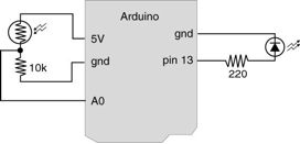
Beginning with the circuit you built last week, try replacing the pots with photocells (You should have two in your kit). Note: you will need to add a 10K resistor (brown, black, yellow) to the circuit as shown in the diagram below.
In the Arduino IDE, in File --> Examples --> Basics, try the ReadAnalogVoltage sketch with the photocell; open the Serial Monitor to see how the photocell responds to different lighting conditions.
Try photocell with what you have built for this week’s homework. So, instead of turning the pots, you can change the amount of light the photocell is getting by making a shadow with your hand or shining light on it.
You can also see this tutorial on using a photocell with Arduino, which includes example code and a good diagram of the most basic circuit setup needed for a photocell.
https://learn.adafruit.com/photocells/using-a-photocell Links to an external site.
Once you plug in the photocell correctly, you can read its value using analogRead as we have been doing for the potentiometers. Remember, you have to make sure that pin number in your code matches the pin where you have physically connected the photocell in your circuit.
Here is a very basic Arduino sketch that just reads the analog input from pin A0 and writes that to Serial.
const int analogInPin = A0;

int sensorValue = 0;

void setup() {
  Serial.begin(9600);
}

void loop() {
  // read the sensor value from the analog input pin
  sensorValue = analogRead(analogInPin);

  // write the sensor value to serial
  // DO NOT WRITE ANYTHING ELSE TO SERIAL
  // Processing is expecting to receive ONLY this number
  // if you send over other stuff (like a nicely descriptive string like "Analog reading ="),
  // Processing will get confused. It may try to interpret the string as if it were a number,
  // resulting in nonsense.
  Serial.println(sensorValue);

  // wait 2 milliseconds before the next loop
  // for the analog-to-digital converter to settle
  // after the last reading:
  delay(2);
}
PART 2 – FORCE SENSITIVE RESISTORS
Replace the photocells in your current circuit with the FSRs (distributed in class). This should simply involve swapping out the photocells with the FSRs (still using the 10K resistors).
Again, try the classic ReadAnalogVoltage sketch with the FSR. Try using the FSR with what you have built for this week’s homework.
You can also see the tutorial here on how to use an FSR sensor with arduino, which has a great diagram of how to do the circuit:
https://learn.adafruit.com/force-sensitive-resistor-fsr/using-an-fsr Links to an external site.
it includes example code. Again, once you plug in the FSR sensor correctly, you can read its value the same way as with the photocell or pot.
PART 3 – PROCESSING
In this section, we begin exploring Processing
1. Download and install Processing if you have not done so yet (www.processing.org Links to an external site.)
2. Play around with some of the examples in File --> Examples --> Basics --> Color
3. Press “Run” 

Congrats! You just made a java applet.
PART 4 – MORE PROCESSING
Influence a Processing program running on your computer with the input from your Arduino board example code.
Open a new sketch in Processing and copy in the code below. What will happen is that the Arduino sketch reads the value from your sensor and writes that value over serial. The Processing sketch will listen to the same serial port and read the value, then that value will influence your Processing sketch. Like this:
sensor –> Arduino sketch –> Serial port –> Processing sketch –> cool visual output from Processing
In addition to using the Processing sketch, at the same time you have to have your Arduino sketch running so that Arduino can send messages to Processing.
/* PROCESSING SKETCH
 * Arduino Ball Paint
 * (Arduino Ball, modified 2008)
 * ----------------------
 *
 * Draw a ball on the screen whose size is
 * determined by serial input from Arduino.
 *
 * Created 21 September 2016
 * Noura Howell
 */

import processing.serial.*;

Serial myPort;
int serialVal = 0;

void setup() {
  // List all the available serial ports
  printArray(Serial.list());
  // Open the port that matches the name of your Arduino port
  // Find the name of your Arduino port in Arduino IDE Tools --> Port
  // Hint: In the line below, change which port you are selecting by
  // changing the 0 to other numbers to refer to other points in the list
  myPort = new Serial(this, Serial.list()[1], 9600);

  // sets the size of the canvas
  size(1000,1000);
  // sets the background color of the canvas in red, green, blue components
  background(40,40,40);
  // sets the framerate at which to update the animations on the canvas
  frameRate(10);

}

void draw() {
 // make the canvas blank again
 background(40, 40, 40);

 // draw a white ball whose size is determined by the value from serial
 fill(255, 255, 255);
 ellipse(500,500,serialVal,serialVal);
}


// READING THE SERIAL MESSAGES FROM ARDUINO

// this "buffer" stores the incoming serial message
String buf="";
// the "carriage return" ASCII code marks the end of a message
int cr = 13; // ASCII return == 13
// the "linefeed" ASCII code marks the end of a message
int lf = 10; // ASCII linefeed == 10

// called whenever serial data arrives
void serialEvent(Serial p) {
  // store the latest piece of the serial message
  int c = myPort.read();

  // if it is not the end of a message
  if (c != lf && c != cr) {
    // then keep adding to buffer
    buf += char(c);
  }
  // if it is the end of a message
  if (c == lf) {
    // convert the buffer into an integer value
    serialVal = int(buf);
    // print it out
    println("val="+serialVal);
    // empty out the buffer so that we are ready to
    // receive new messages
    buf = "";
  }
}
Try it with pot, photocell, and FSR.
Technical Hints
Telling Processing which serial port to listen to
You may have to modify the Processing sketch so that it knows which Serial port to listen to. If you go to Arduino IDE Tools --> Port, you can see that there are several different serial ports on your computer. Find the one that matches your Arduino and remember its name. Then, run the Processing sketch. It will print out a list of all the serial ports in the black rectangle at the bottom of the Processing IDE. Find your Arduino serial port name in this list, and figure out which <strong>index</strong> in the list, or which position in the list, it is in. The first element of the list is referred to as index 0, the second element of the list is referred to as index 1, and so on. In the Processing code there are comments explaining where to specify this index in the code (in the code it says, "Hint: In the line below, change which port you are selecting").
Changing your code and restarting
When making changes to Arduino code or Processing code, you have to restart both Arduino and Processing sketches in this order:
1. Stop Processing animation by closing the animation window.
2. Re-upload code to Arduino. Make sure the Serial Monitor is closed.
3. Restart Processing sketch.
Arduino's serial monitor and Processing can't run at the same time
To run the Processing sketch, make sure Arduino's Serial Monitor is closed. Only one thing can read from serial at a time.
Connecting the FSR sensor
In order to make the FSR sensor part of the circuit you have to attach it to wires. We suggest following these steps to ensure a secure connection. If you take shortcuts, you might save a few minutes up front, and it might work just fine for a little while, but then it might mysteriously stop working and you could waste hours trying to find the problem.
Connect the following pieces as shown. We will provide these pieces to you.
Then secure all the connections with electrical tape.
Additional resources
Sparkfun has a tutorial on making Arduino and Processing communicate via Serial:
https://learn.sparkfun.com/tutorials/connecting-arduino-to-processing Links to an external site.
Homework
Programming
Create an interesting visualization on your computer that could be influenced by the input from the sensors you have (pot, photocell, FSR, or combination of them). You can use Processing (or any other language you like) in writing the program. Report on your results in the lab submission.
Mechanical
Create a mechanical construction for your FSR that distributes or focuses physical force that is applied. Think about everyday objects (toothpaste tube, entrance mat, paintbrush, pipette, etc.) and how you measure the pressure or force applied to them
 Find Rubric